All polygons are converted into graphs and put into a
list of graphs (graphlist). See graphs
structure
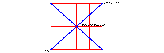
Assuming the input data is supplied in doubles, the coordinates
will be converted to 64bit integers.
This is done using two scale factors, DGRID
and GRID.
DGRID defines the accuracy the user wants
an accuracy of two digits means DGRID should be set to
DGRID = 0.01
Although in the boolean algorithm the accuracy is higher, the end result
will be rounded to the DGRID.
GRID defines the number of digits the boolean algorithm will use to
calculate extra intersection.
If for instance two segments intersect
the intersection point does not have to be on the GRID.
If the GRID would be set to 1, there would be no integer number in
between to define this intersection point.
With the GRID set to 100 there is place for those intersections, in
this case the intersection point would be
(50,50).
In fact the algorithm uses a kind of integer fixed point calculation
for coordinates, the fractional part is always fixed (least significant
2 digits) .
For instance if the DGRID = 0.01 and GRID = 100 and the original polygon
point is (1234.56,4567.89).
The following coordinate will be used inside the boolean algorithms
(12345600,45678900).
So multiplied by 1/DGRID converts the doubles to integers.
GRID = 100 means multiply those integers with an extra factor
to create space for the boolean algorithm to create intersections in between.
In the end all points will be converted back to double with an accuracy
of DGRID.
This means all new intersection points will also be rounded to the
DGRID in the end, if the user wants those intersection to be more accurate
than his input data, the DGRID should be set smaller than the accuracy
of the input data.
Round
The boolean algorithm works internal with "64 bit integers",
all the coordinates need to be rounded to a GRID.
Currently the GRID is set to 100. This means that all
input coordinates will be rounded at two decimals.
Since every coordinate is rounded to GRID, the minimum
length of a segment in the input data can be one GRID (zero length segments
are removed). Diagonal the minimum length will be "sqrt(GRID)". Two such
segments can still intersect since GRID is set two 100.
minimum length segments
MARGE
What is defined as small is set by the factor MARGE,
which can be set by the user. MARGE is heavely used all through the algorithm.
It takes care of preventing glitches, because it makes nodes snap to lines and
other nodes. So it can be seen as a snapfactor. It is important to understand
that the snapping is not the same as rounding to a GRID. Many graphical drawing
tools work with a GRID, even without knowing it the user will introduce glitches
into his data. Next to that, many graphical interface formats super impose another
GRID on top of the data, resulting in even bigger glitches. The MARGE factor
takes care of such unwanted effects. In remove
glitches. gives an example, it may look that the drawing is heavely
changed by this action, but since the MARGE is normally small compared to the
size of the polygon itself, this is not really the case. It does not make much
sence to set MARGE smaller than the GRID, since everything is rounded to GRID
first. Normally the GRID is set much smaller than MARGE. Even if MARGE takes
care of snapping vertexes, in the end every intersection wil be rounded to the
GRID again. This is not a problem, because snapping problems are solved at that
stage.
Assume the following settings for DGRID, GRID and
MARGE:
DGRID = 0.01;
MARGE = 0.1;
Those factors are all based on the points that are put in the original
polygons using doubles for the vertexes.
The coordinates and factors used by the boolean algorithm are scaled
properly, before doing an operation.
MARGE = 0.1 results in snapping/breaking segments to reach another
vertex when the distance to this vertex is smaller than 0.1.
Just before converting the polygons into graphs the factors will be
set as follows:
DGRID
= 1/DGRID;
MARGE =
MARGE*GRID*DGRID;
With DGRID=0.01 , GRID=100, MARGE=0.1 this would result in MARGE=1000
that is used inside the boolean algorithm.
After the boolean operation, they will be set back to the original
value.
remove glitches
simplify
Simplify works on the input data, it makes sure that
the input data does not contain segments that are not needed and could
cause problems.
Simplify means removing redundant coordinates, for instance
the segment coordinates are at the same position. This would result in
a zero length segment, which is impossible to handle because its direction
is not defined.
Also very small segments will be removed. What is small
is defined by the factor MARGE.
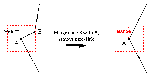
In removing zero-links.
node B is removed since it is within MARGE distance to node A.
removing zero-links
If three nodes are on the same line, the middle node can be removed.
Again MARGE is used to decide if the nodes are on the same line. At last
if links add nothing extra to the area defined by
the polygon, they will be removed. What is nothing in this case is decided
by the MARGE factor also.
removing links that add nothing to the area of the
polygon
The principle behind the implementation of simplify is as follows. Find
links to be removed, mark those links for removal, create a new link to
replace the links that will be removed. The new link will be added to the
end of the list. The current link will be removed directly. Repeat this
until there are no more changes to be made, at the end of the list, we
start at the beginning again. The total number of links in the graph is
used to trace if we are finished. Once we passed the total number of links
in the graph, without make a change, we are done. The reason for this way
of working is that removing a link, can result in other links to become
a problem. So one cycle with no changes makes sure everything is oke.
merge into one graph
The calculation of the intersections within graphs and
between other graphs, is based on scanlines. For this all segments/links
of the seperate graphs are merged into one big graph structure. It is now
one big list of segments/links, that can be used to find the intersections
between all links. The original polygon/graphs can still be found back
because of a unique number added to each link object, that tells to which
original polygon it belonged. The one graph structure is ideal for scanline
algorithms ( See Scanbeams.
), because the links in the graph can be sorted without loosing the structure
of the drawing. Only the links get a different order in the list, the position
of the nodes concerning (x,y) will not change.